Week 17 Blog - Project Development
Our chemical device that my group did is the half boiled egg maker. The objective of the half boiled egg maker was to be able to cook up to 4 eggs perfectly without overcooking or undercooking them. Here is our initial design:
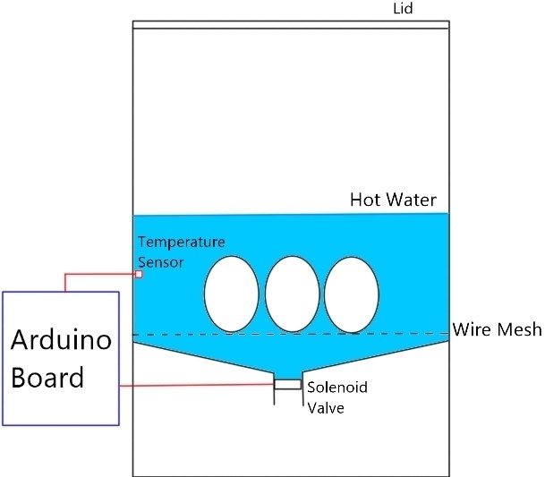
When the temperature sensor detects a change in temperature, it will send a signal to the Arduino board to start the code and wait for 7 mins to cook the egg. After 7 mins, the Arduino board will open the valve for another 1 min so that the hot water will be drained so will close when it is done.
My team for this project is Bjorn as our Chief Executive Officer, Roy as our Chief Financial Officer, Vernon as our Chief Safety Officer and Me as the Chief Operating Officer. We allocated the task based on our competency.
Arduino Programming: Done by Nigel
Designing CAD for 3D Printing: Done by Bjorn
3D Printing of Parts: Done by Roy and Vernon
Assembly of Prototype: Done by Whole Group
Gathering of Materials: Done by Whole Group
Here is our initial Gantt chart: However we did not follow the chart due to unforeseen issues so here is our final building schedule:

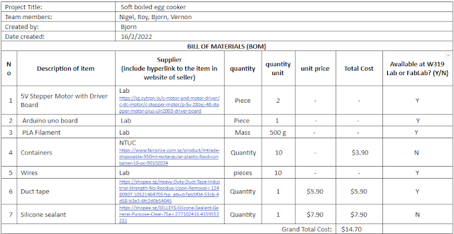
Finalized Bill of Material:
Arduino Programming (Done by Me)
We wanted to stepper motor to be able to having a 7 mins delay before turning 90 degrees for 1 min and then turning back to a close position. This will be run when the button in the board is pressed. In order to start, I had to copy and paste the code from the seller's website as it contains the code which allows the motor to move. Then in the void loop, I start off with the Toggle Button code in my Arduino Practical blog (DC Motor part) since I will be using it to run the code. Then I added a delay for 7mins (420000ms). The stepper motor has 2048 steps per revolution so in order for it to turn around 90 degrees, I added the for loop. Initial a (number of steps) = 0, a will keep on adding until it reaches 500 steps (90 degrees). Now I have to add the delay for every step and the direction. The minimum delay I found in the website is 2ms per step so I add a delay of 2ms in the for loop. OneStep(false) is the direction of the step which is defined by the initial code. Currently, it is turning at a clockwise direction. For that, we wanted it to stay at this position for 1 min in order for the all the hot water to drain out and hence we added another delay for 1 min (60000ms). Lastly, we wanted the motor to turn back to its original position, so I copy the first for loop and paste it at the bottom and changed the direction to anti-clockwise, OneStep(true) to OneStep(false).
Here is what the code look like:

Design of CAD and Valve Mechanism Schematic (Done by Bjorn)
Link to his blog: https://cp5070-2021-2b02-group3-bjorn.blogspot.com/2022/02/project-development.html
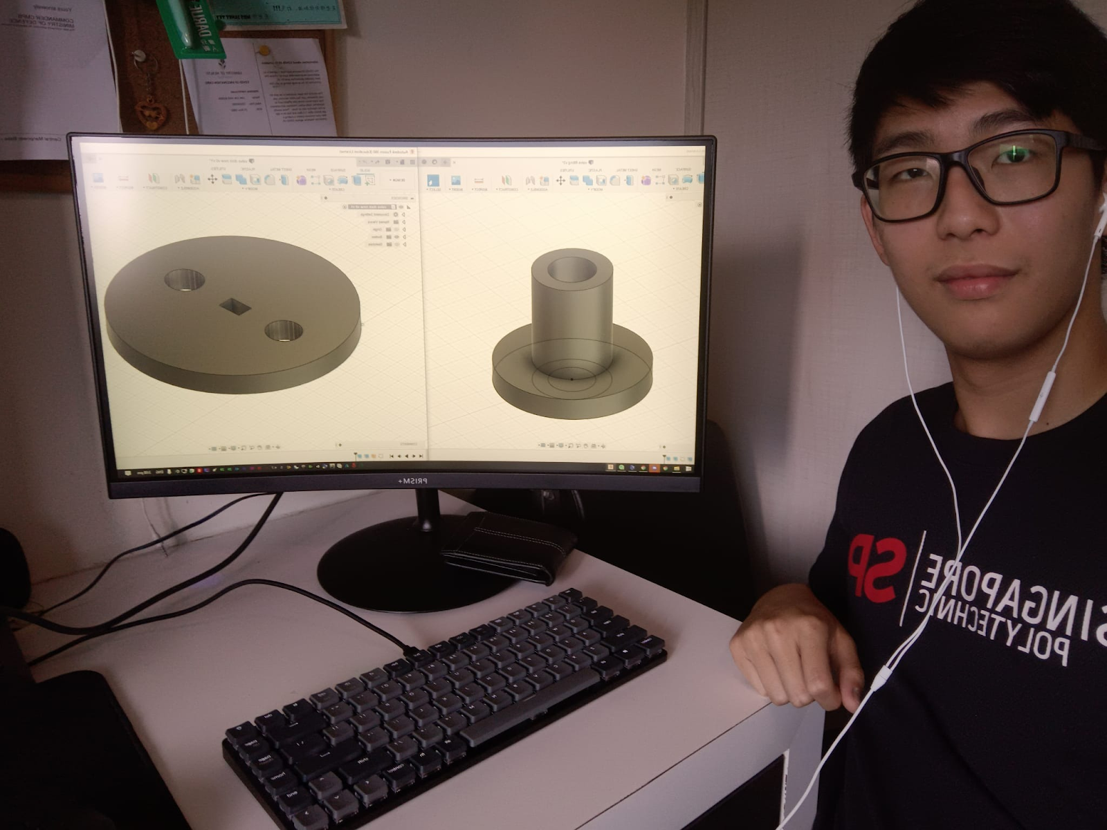
Design of CAD for 3D printed parts

CAD of Valve Disk

CAD of Valve connection
For the designing and printing of parts, we had to design and print 2 parts for our prototype, valve connection, and disk, 2 of each.
For the valve disk, I created a circle of diameter 50mm, drew 2 smaller circles of diameter 7.6mm and a small rectangle in the middle of dimensions 3.6mm x 5.2mm. Lastly, I extruded the sketch by 5mm.
For the valve connects I drew a larger circle with a diameter of 25.4mm, a middle circle of 12.7mm, and a small circle of 7.6mm. I extruded the outer circle by 5mm, the middle circle by 21.55mm, and left the small circle not extruded.
I designed the middle hole of the valve disk to be the same as the stem of the stepper motor so it fits snugly onto the stepper motor. Since the tube we purchased had an internal diameter of 12.7mm we also designed the outer diameter of the valve connections to be 12.7mm to fit the tube. The holes of the disk were designed to have a sufficient flow rate when water is being drained. The thickness and height of the disk and valve connection were chosen to have a smaller form factor for our valve mechanism.
Hero Shot of CAD
Valve Mechanism Schematic

Brainstorming of the Prototype (Done by Roy)
Link to his blog:https://cp5070-2021-2b02-group3-roy.blogspot.com/2022/02/project-development-entry.html
For the assembly process, from what Bjorn designed and Nigel coded, my main task that I spent the most time on was to get the prototype working as well as come out with new ideas when the old failed.
Initially, we were following a different design:

However, due to issues we faced, we had to drop this idea completely. So the team and I started brainstorming. I came out with the idea to try to implement a vacuum and to perhaps use a tap as a start-stop valve.

But the final idea that we implemented was thought of by Vernon. I did a sketch after the idea has been selected and tried to visualize the design:

We spent the next day in school to try to implement the design, such as fabricating the initial tube, mounting of motor, and testing the mechanism:
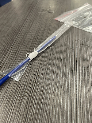
However, the tube we fabricated was proven to not be durable enough, hence in the end we used a straw instead, which meant that we had to rebuild the entire prototype by dismantling it.
3D Printing of Parts (Done by Vernon)
Link to his blog: https://cp5070-2021-2b02-group3-vernon.blogspot.com/2022/02/project-development.html
To use the 3D printer in the workshop we had to book the printer we were going to use. Before going to workshop to use the printer, Bjorn had sent me the file of the CAD parts he designed. My job was to goto W3 to print and troubleshoot if problems were to arise.
Here is the Cura setting I used for the printer which was the Creality ender-3. I used the same settings for both parts we printed.

A small issue that arose was the sizing of the square was a little too small which we found out after the first print. It was a easy fix as we just need to adjust the length and width of the square.
Here is the photo of the parts printed.

In total i printed 5 parts. It took slightly more than 4hours to print all 5 parts. The first part was defective as it was the wrong size.
Here is a short time lapse for the Disk.
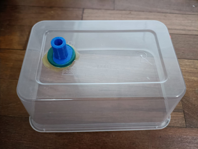
Firstly, we connected the valve connection to the container using some silicone sealant.

We then started on the wiring of the motor to the arduino board. The 5V pin of the Arduino board was connected to the '+' pin on the driver board. the ground pin on the Arduino Board was connected to the '-' pin on the driver board. Pins 9, 10, 11, 12 was connected to the driver board as stated in the Arduino code.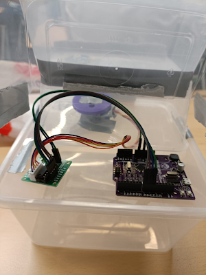
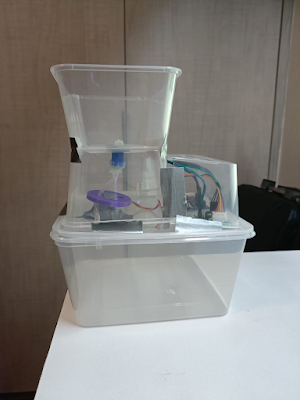
Lastly, we added the waste container on the bottle and the electronic housing.

Here is a video on our valve mechanism working:
Here is the Cura setting I used for the printer which was the Creality ender-3. I used the same settings for both parts we printed.
Here is the photo of the parts printed.
Here is a short time lapse for the Disk.
Integration of all the parts (Done by whole group)

We then started on the wiring of the motor to the arduino board. The 5V pin of the Arduino board was connected to the '+' pin on the driver board. the ground pin on the Arduino Board was connected to the '-' pin on the driver board. Pins 9, 10, 11, 12 was connected to the driver board as stated in the Arduino code.
Lastly, we added the waste container on the bottle and the electronic housing.
And this is a video of how our prototype work:
Problems and Solutions
1. Motor broke due to rusting

2. Problems with our Initial design
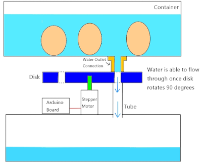

Our initial idea was for the disk to block the flow of water when the holes are not aligned but when the disk turn 90 degrees, the holes will be aligned causing a flow.

3. 12V Solenoid Valve
Link to all the files:
https://drive.google.com/drive/folders/1cXuNUvqClMpqXbsQs_gDCVzex5HCwjKA?usp=sharing
Thanks for reading!!
No comments:
Post a Comment